HOME
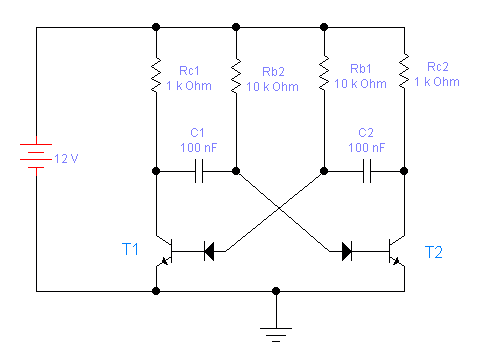
ASTABLE MULTIVIBRATOR
 This is the schematics of an astable multivibrator.
This circuit outputs rectangular signal at points P1 and P2.
It is made out of two amplifiing stages.Output of the first stage
is connected to input of the second via condensor C1 and
output of the second stage is connected to input of the first via condensor C2.
Since both stages are inverters this is a system with strong positive feedback.
When it is operating one transistor is always in saturation and the other is in
a open circuit state.
This is the schematics of an astable multivibrator.
This circuit outputs rectangular signal at points P1 and P2.
It is made out of two amplifiing stages.Output of the first stage
is connected to input of the second via condensor C1 and
output of the second stage is connected to input of the first via condensor C2.
Since both stages are inverters this is a system with strong positive feedback.
When it is operating one transistor is always in saturation and the other is in
a open circuit state.
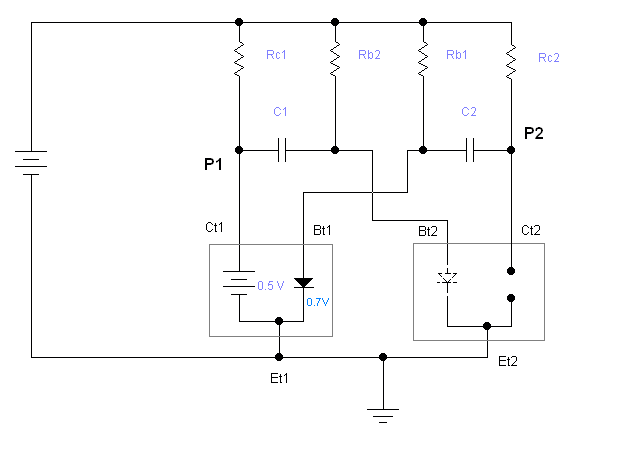
We will assume that we started analyzing the circuit in the midle of it's operation
just at the moment when T1 went to saturation.(Important thing about starting analyisis at this point in time of
operation is that C1 is charged in that way that it gives negative voltage to the T2 base-emiter junction.)
So T1 is in saturation and it's
collector-emiter voltage is 0.5V and it's base-emiter voltage is 0.7V.
It is conducting from both collector and base.(It is important that we notice that
there is no input resistance and that base-emiter acts just like diode.)
So we allmoast can look at T1 as short circuit.
When T1 is in saturation T2 is in open circuit state.
Voltage of point P1 is allmoast at ground because T1 is in saturation.
Voltage of point P2 is at Vcc because T2 is in open circuit state.
Since T2 is in open circuit state any or all the currents can go only through T1.
We are interested only in currents that flow trough the condensors.(Do not be confused
because some resistors are in parallel with the branches of interest.)
So here it goes:
- C1 is connected to (allmoast) ground trough the collector of T1
and it's other pin is connested to Vcc trough Rb2.So it is charging and the speed
of this charging is limmited by Rb2.
(In parallel with the branch C1-Rb2 there is Rc1, but this is of no interest to us.)
- C2 is connected to (allmoast) ground trough the base of T1 and it's other pin is connested to Vcc trough Rc2.
Since Rc2 has lower value than Rb2, C2 is charging faster than C1.
(In parallel with the branch C2-Rc2 there is Rb1, but this is of no interest to us.)
So in this quazi-stable state both condensors are "conducting".
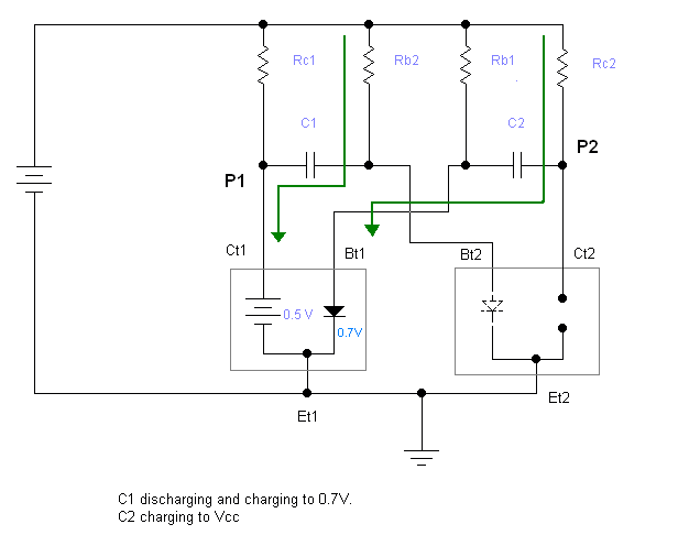
C1 is discharging from negative voltage and charging to 0.7V .
C2 is discharging from -0.7V and charging to (allmoast) Vcc.
C2 is full and ready before C1 reaches the treshold voltage of 0.7V .
So what happens now is that when C1 reaches 0.7V point P2 goes to ground and
positive side of C2 gets connected to ground and negative side stayes connected
to base of T1 which pushes T1 in open circuit state (and T2 in saturation).
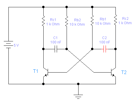
EQUIVALENT SCHEMATICS
Rc1=Rc2= 1K ohm
Rb1=Rb2= 10K ohm
C1=C2= 100nF
Power supply voltage = 5 V
What is inportant to know is that when the transistor is in sturation voltage between
it's collector and emiter is about 0.5V (which is lower than base-emitter treshold)
and that when in saturation base-emiter is acting just like diode so there is no
input resistance.(Note: Emiter-Collector saturation voltage can be even lower than 0.5V)
So when multivibrator is in operation both collector-emiter and base-emiter
of the one of the transistors that is in saturation can be looked apon as
of short circuits. The other transistor is in open circuit state since
the base emiter voltage is bellow 0.7V or negative (base-emiter diode is
inversely polarised or the voltage is bellow 0.7V so there is no collector current).
Since the only one transistor that is conducting is the one in saturation
both condensors are charging trough it. The condensor that is charging trough
the base resistor is charging slower than the condensor that is charging
trough collector resistor.This is because base resistor has higher value than collector resistor.
When the slower one fills (from negative) to 0.7V the transistor
that was in open circuit is starting to conduct which means that negative voltage
is applyed to the base of the transistor in saturation because positive side of charged
condensor is being connected to the ground.Since negative voltage is applyed to the transistor
in saturation it stops conducting and switches to open circuit state and the other transistor
goes to saturation.
The frequency of output signal is calculated like this: f=0.7/(Rb*C)
(providing that the circuit is simetrical)
If you want to power it with a voltage higher than 5V you need diodes
at the bases of the transistors
to protect them against the reverse voltage.